 Over 20 years of experience in Sterile, Biological Pharmaceutical and Hospital Facilities Engineering Design, Construction and Validation.


24 Apr Cleanroom Differential Pressure Explained – Part 1: Static Balancing
1. Introduction
In our previous article, Leakages Calculation, we introduced the basic principles of cleanroom pressurization. We also explained how to achieve positive differential pressure in cleanrooms. In simple terms, a pressurized cleanroom works by limiting air leakage through the room envelope and compensating for those leakages with the correct amount of fresh air.
Although this is a relatively simple physical concept, I still see frequent misunderstandings in real HVAC design discussions. Most of them relate to the interaction between air leakage, return airflow and differential pressure. After receiving several questions on this topic, I decided to write this article to explain the concept in more detail.
In this article, I will explain how cleanroom differential pressure behaves in a statically balanced HVAC system. I will also show why even small changes in leakage area can cause a significant drop in room pressure if the system is not readjusted.
2. Types of Differential Pressure Control
In general, there are two main ways to control differential pressure in a cleanroom: static control and dynamic control.
Static pressure control keeps the supply airflow constant, usually by means of CAV (Constant Air Volume) dampers. The system then adjusts the return airflow with manual balancing dampers. If the room pressure moves away from its setpoint because of leakage changes or operating variations, the maintenance team must readjust the return dampers manually to restore the required differential pressure.
Dynamic pressure control, by contrast, uses VAV (Variable Air Volume) dampers or other modulating airflow control devices instead of manual dampers. In this case, the return or extract airflow changes continuously in response to the signal from a differential pressure sensor installed in the room. In other words, the system automatically makes the same correction that a statically balanced system would require maintenance personnel to make manually.
Today, dynamic control is by far the most common solution in pharmaceutical cleanrooms. It responds faster and provides better stability when operating conditions change. However, engineers still design and install static balancing systems, and these systems can work perfectly well in the pharmaceutical industry when the design is sound, the commissioning is done properly, and room leakage remains under control.
3. Numerical Example of Cleanroom Differential Pressure in a Statically Balanced System
To explain cleanroom differential pressure more clearly, let us look at a simple numerical example based on a statically balanced HVAC system.
Let us assume we have a cleanroom that must be maintained at a positive pressure of 30 Pa. The room has only one door, measuring 2.0 m high by 1.0 m wide. For the sake of simplicity, we will assume that all leakage takes place only through the gap between the bottom of the door and the floor.
As explained in the previous article, “Leakage Calculation”, a 2 mm gap under the door corresponds to an equivalent leakage area of 0.0020 m². At 30 Pa, this gives a leakage airflow of 32.6 m³/h.
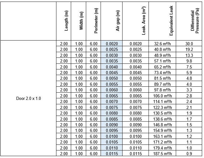
If the system remains statically balanced, the outdoor air flowrate also remains constant at 32.6 m³/h. This means that the leakage airflow available to pressurize the room stays constant as well. However, if the door gap increases, the same airflow must pass through a larger opening area. As a result, the room differential pressure decreases until a new equilibrium is reached.
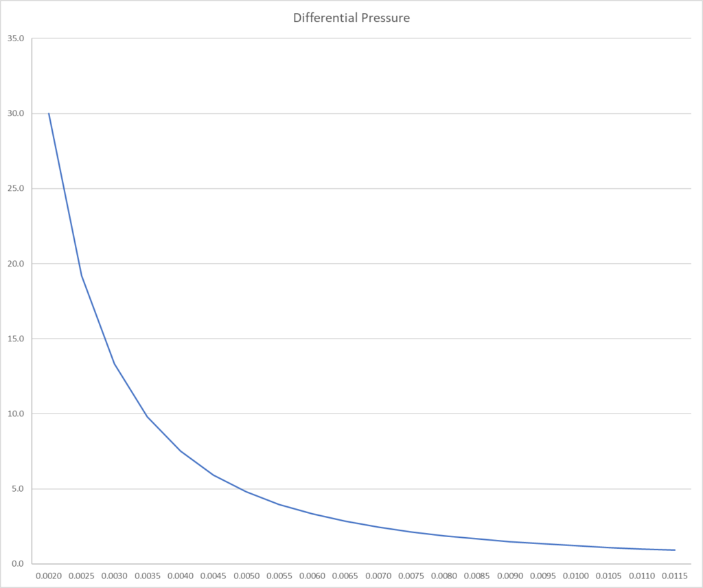
This is exactly what the graph below shows. Starting from the initial condition of 30 Pa with a 2 mm gap, the room pressure drops rapidly as the gap increases. The pressure loss is particularly significant at the beginning. In other words, a relatively small increase in gap size causes a large reduction in pressure.
This happens because the relationship between differential pressure and leakage area is not linear. For a fixed leakage airflow, the room pressure varies approximately with the inverse square of the leakage area.
In practical terms, this means that even a small deterioration in the door sealing system can cause a substantial loss of cleanroom differential pressure if the system is not readjusted. Typical examples include wear of the bottom seal or degradation of the door gasket.
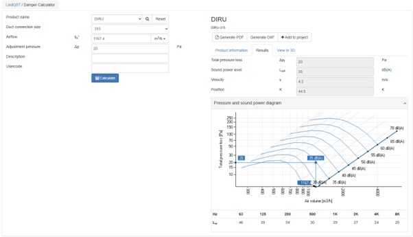
The system is initially balanced by setting the return airflow to 1167.4 m³/h, calculated as:
1200 − 32.6 = 1167.4
where 1200 m³/h is the total supply airflow and 32.6 m³/h is the leakage airflow required to maintain the room at 30 Pa.
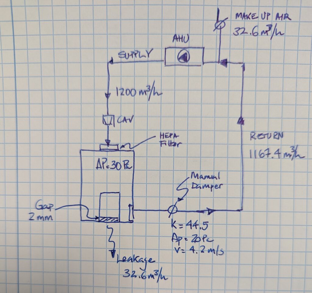
To achieve this operating point, we selected a 315 mm iris damper in the return duct, with a total pressure drop of 20 Pa. The Lindab selection chart is a very useful tool for evaluating the behavior of the damper at the design airflow. For this duty point, the damper gives an air velocity of approximately 4.2 m/s and a sound level of about 35 dB(A), making it a very reasonable choice for this application.
As explained above, a statically balanced cleanroom is not a perfect system. Over time, the leakage area may increase due to wear, seal deterioration or failure of the retractable door seal.
Let us assume that the leakage area increases from 0.0020 m² to 0.0100 m². Under these conditions, and with no active pressure control, the room differential pressure would fall from 30 Pa to approximately 1.2 Pa. In a pharmaceutical facility, this would immediately trigger a deviation because the room would be operating outside its pressure specification.
If the door is not repaired, the pressure can still be restored by increasing the outdoor air flowrate. Based on the previous calculations, the system would need 163.1 m³/h of outdoor air to bring the room back to 30 Pa.
Because the total supply airflow remains fixed at 1200 m³/h, the return airflow must be reduced accordingly:
1200 − 163.1 = 1036.9 m3/h
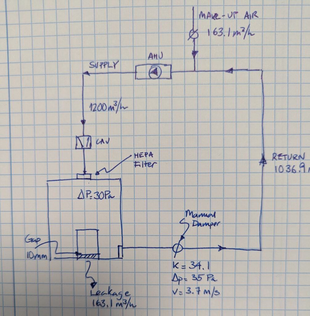
This means that the return damper must be closed further. The required adjustment can be determined using the manufacturer’s chart, by moving from the initial operating point to the new return flow and reading the corresponding k-value.
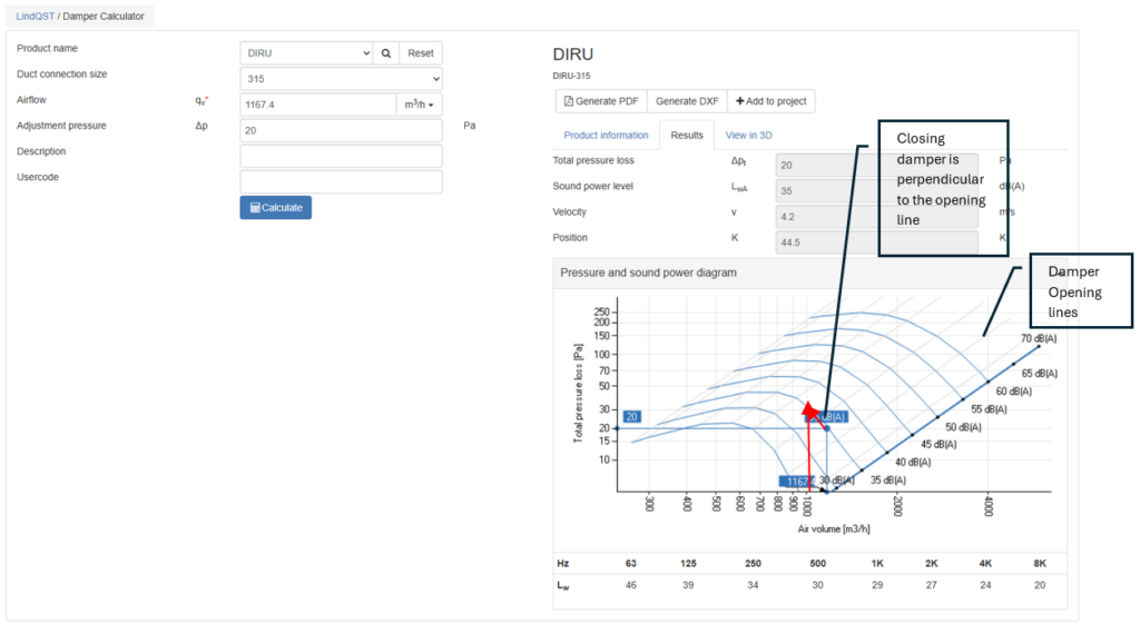
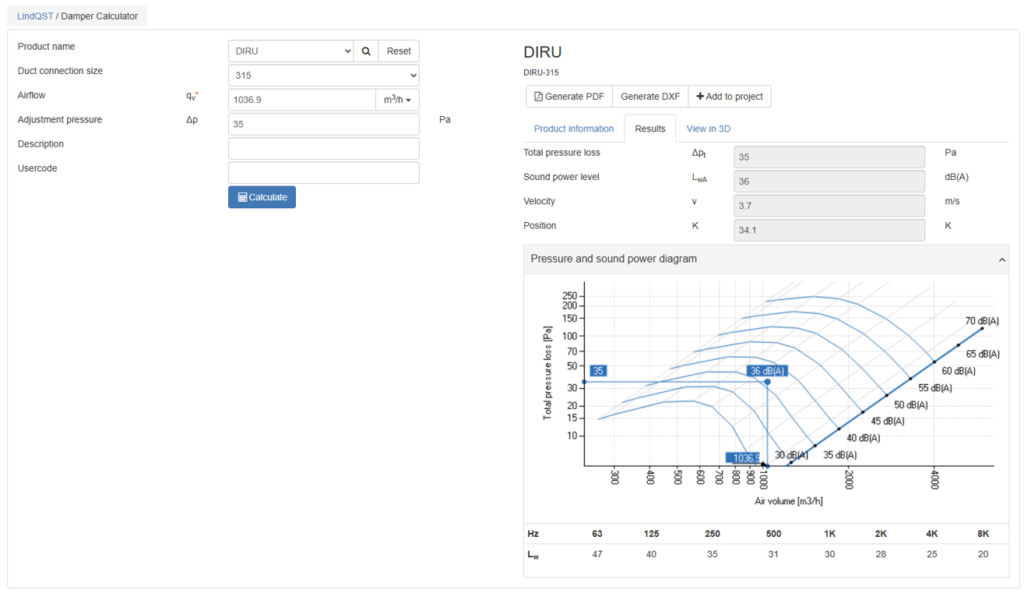
We can see that the new total pressure drop across the iris damper must be approximately 35 Pa. In other words, the damper setting changes from k = 44.5 to k = 34.1, which means that the damper must be moved to a more closed position.
The opposite situation may also occur. The leakage area may decrease as a result of repairs, sealing improvements, or even the removal of a door.
Let us assume that, after a series of improvements to the room enclosure, the room differential pressure rises from 30 Pa to 37 Pa. This corresponds to an equivalent leakage area of 0.0018 m².
In that case, the system must be rebalanced by increasing the return airflow slightly, from 1167.4 m³/h to 1170.6 m³/h. This is done by opening the return damper, that is, by moving to a higher k-value.
In this example, the adjustment is very small, and the new setting would be approximately k = 47.6.
4. Conclusions
This simple example clearly shows both the strength and the limitation of static pressure control in cleanrooms. The concept is straightforward and robust: if the leakage airflow is known and kept under control, the room can be pressurized reliably by maintaining the correct balance between supply airflow, return airflow and outdoor air.
However, the example also shows that a statically balanced system is inherently sensitive to changes in leakage area. Even relatively small variations in door sealing, envelope tightness or room leakage paths can cause a significant change in cleanroom differential pressure, requiring manual readjustment of the return damper in order to restore the original pressure setpoint.
In other words, static pressure control can work perfectly well in pharmaceutical cleanrooms, but only if the system is well designed, properly commissioned and the room leakage remains reasonably stable over time. This is also one of the main reasons why dynamic pressure control systems are often preferred in modern cleanroom design.


No Comments